

of Equipment
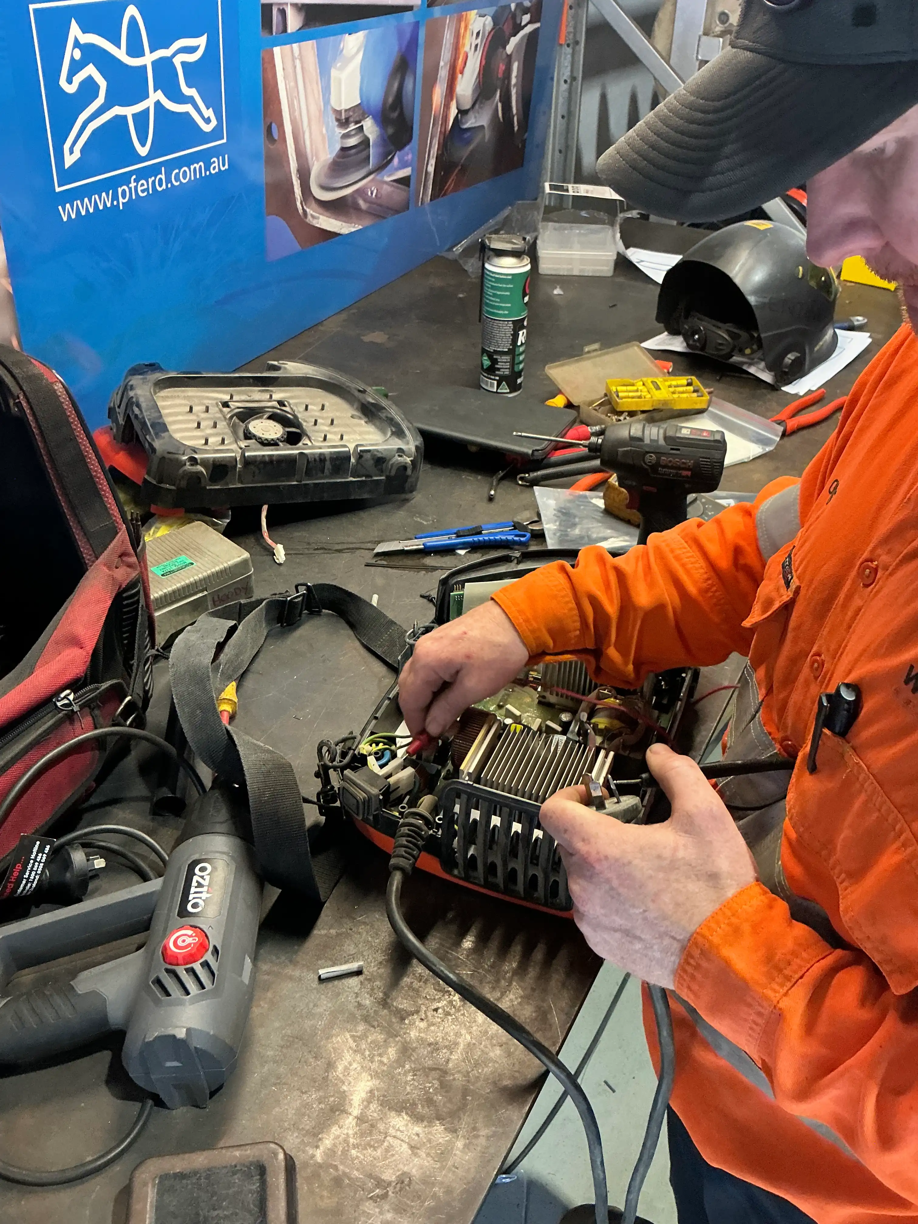
Maintenance
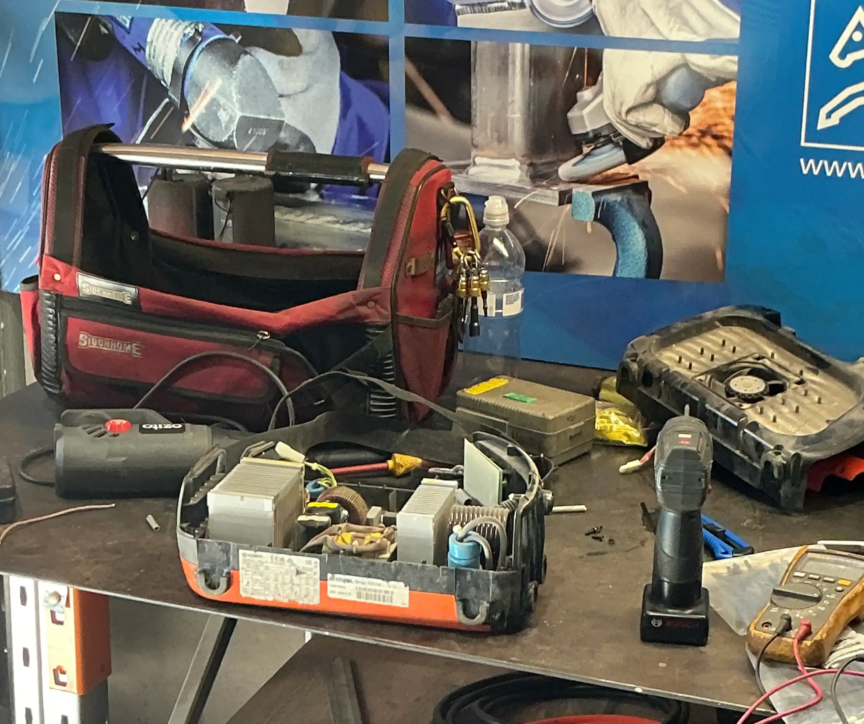
Accurate voltage indication on welding machines is fundamental...
VRD (Voltage Reduction Device) Testing
VRD testing ensures a welder's safety features lower the open-circuit voltage (OCV) to safe levels when idling. What we check:
-
Safe Open-Circuit Voltage (OCV): Confirms the VRD drops the idle voltage down to safe regulatory thresholds—typically below 35V DC or 25V AC (often around 12V to 24V) when no welding arc is struck.
-
Resistance Threshold Sensing: Verifies that the VRD detects a load resistance below 200 ohms (such as when an electrode touches the workpiece) and switches the welder to full output power. It also checks that it switches back to a reduced-voltage state when resistance rises above 200 ohms or the electrode is removed.
-
Switching Response Time: Measures the speed at which the device transitions between high and low voltage states. Compliance standards (such as AS 1674.2) generally require the switch time to be under 0.5 seconds for DC machines and 0.3 seconds for AC machines.
-
Visual/Indicator Checks: Ensures operational warning lights (such as a green light for safe/reduced OCV and a red/flashing light for full/live output) function correctly
Verifies the electrical safety and integrity of welding machines
IR (Insulation Resistance) Testing
IR Testing on a welding machine evaluates the integrity of internal electrical insulation to prevent electric shock or short circuits. In Australia, this is governed under AS/ NZS 3760 and related standards like AS/NZS 60974.4.
Standard Requirements & Parameters (Australia)
-
Test Voltage: Typically 500V DC applied by an insulation resistance tester (Megger)
-
Pass Threshold: Must generally be greater than 1 MΩ for Class I welding equipment.
-
Earth Continuity Check: Often paired with an earth resistance check (must typically be ≤ 0.1 ohm).
-
Inverter Precaution: If the welding machine uses sensitive electronic inverter boards, check the manufacturer's user manual first, as high DC test voltages can potentially damage solid-state electronics.
General Testing Procedure
-
De-energise & Isolate: Disconnect the welding machine completely from the mains power supply.
-
Visual Inspection: Inspect the power lead, plug, earth pin, housing, and welding cables for cuts, cracks, or burns before electrical testing.
-
Primary Circuit to Earth: Connect one lead of the MΩ to the combined live/neutral (or tied primary terminals) and the other lead to the earth pin/chassis. Apply 500V DC and record the resistance value.
-
Secondary Circuit (Welding Side) to Earth: Test the welding output terminals against the protective earth/chassis to verify no breakdown exists between the secondary welding side and the frame.
-
Record & Tag: Log the values, apply a new test tag with the test date and retest due date, or red-tag and remove the unit from service if it fails.
A thorough inspection followed by specialized electrical tests — like continuity, insulation resistance, and leakage current — to ensure operator safety.
Learn MoreVerifying that output parameters — including voltage, amperage, and wire....
Welding Machine Calibration
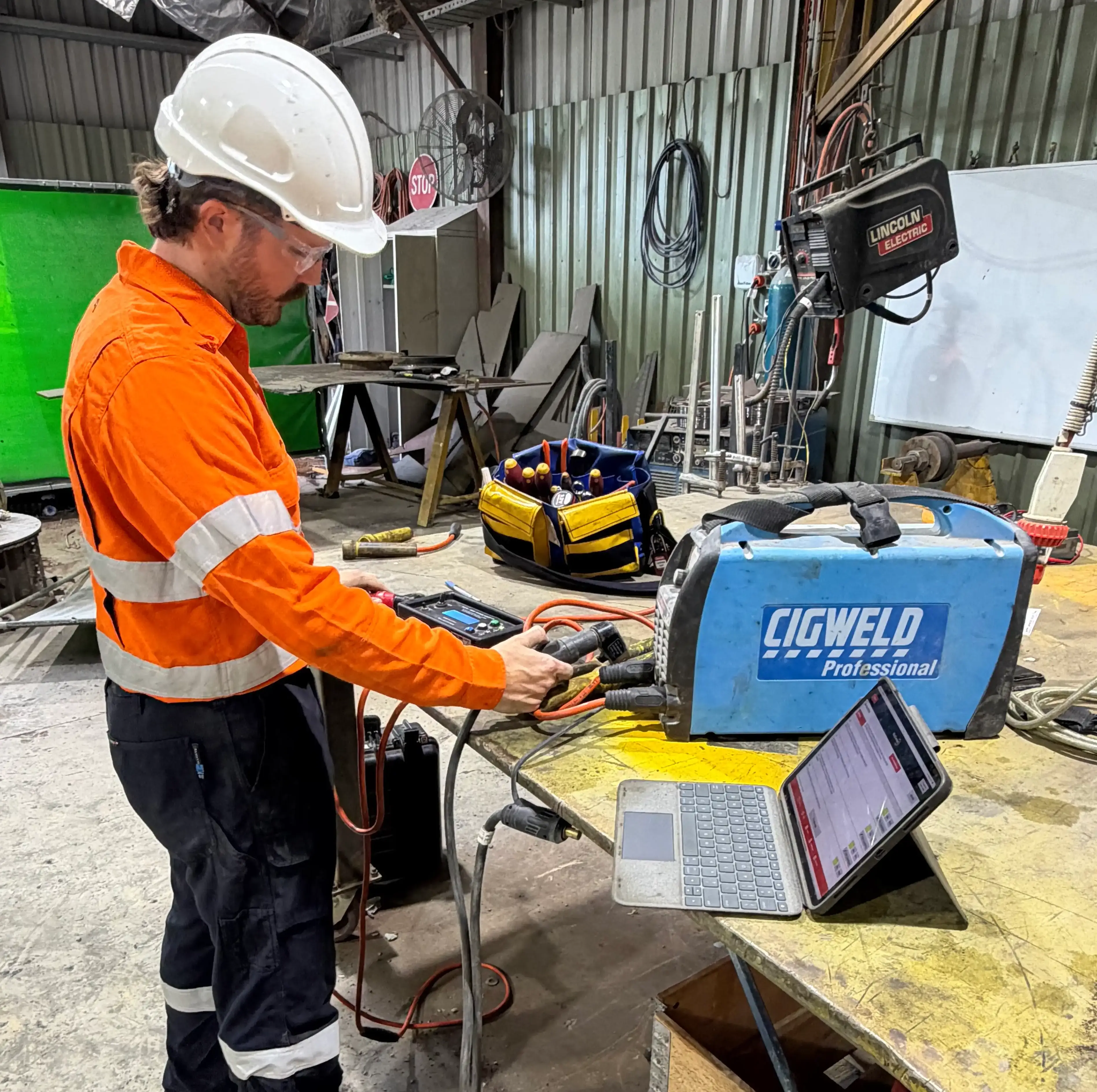
Welding Machine Calibration is the process of measuring, verifying, and adjusting a welding machine's electrical and physical outputs — such as voltage, amperage, wire feed speed, and shielding gas flow — against a known, certified standard to ensure accuracy and compliance.
What Happens During Calibration?
• Measurement: Technicians connect the welding power source to a specialised load bank or calibration station to test actual output levels across multiple step points (for example, low, medium, and high current settings).
• Comparison: The real-time output (read via calibrated external tools like ammeters and voltmeters) is compared to what the machine's display or dial claims it is producing.
• Adjustment: If the discrepancies exceed permissible tolerances (often defined by standards like ISO 3834, EN 50504, or the Australian Welding Code of Practice), internal controls or software are adjusted to align the machine.
• Certification: Once verified, the machine receives a calibration sticker and a formal certificate detailing its operational accuracy.
Key Parameters Evaluated
• Welding Current (Amperage): Controls heat input and weld penetration.
• Arc Voltage: Affects arc stability and bead width.
• Wire Feed Speed (MIG/MAG): Ensures consistent filler metal deposition.
• Shielding Gas Flow Rate: Verifies proper atmospheric protection of the molten weld pool.
Why It Matters
• Quality & Consistency: Prevents defects like poor fusion, porosity, or weak joints.
• Compliance: Fulfills requirements for regulated industries such as aerospace, automotive, structural steel, and pressure vessel fabrication.
• Frequency: Standard-grade equipment is typically calibrated every 12 months, while precision-grade or heavily used machinery is calibrated every 6 months, or immediately following a major repair.